This application note will outline proper setup and measurement procedure for performing dual band measurements with a Copper Mountain Technologies 4-port Cobalt VNA. This example setup features a C4409 4-port 9 GHz Analyzer and uses two ports for measurements in a low frequency band, while the other two ports are used for measurements in a separate, higher frequency band. Measurements with this dual band setup are not simultaneous but allow the user to quickly switch back and forth with the simple click of a button.
The dual band measurement setup is ideal If you have a 4-port frequency extension compatible VNA and are working in an application that deals with multiple frequency ranges. For example, some 5G applications deal in a low frequency band (below 6 GHz) as well as the mmWave frequency band.
Equipment Required
Frequency extension compatible 4-Port Cobalt VNA (C4209, C4409, C4220, C4420)
At least one set of frequency extenders (separate bands are required if using two sets of extenders) extender selection is determined by the DUTs being used
500 MHz bandpass filter (DUT #1)
77 GHz bandpass filter (DUT #2)
Measurement Procedure
Connect extender set to ports 1 & 2.
Connect test cables to ports 3 & 4.
Calibrate at the end of the test cables on ports 1 & 2.
Connect DUT #1 to ports 1 & 2 and complete the measurement.
Go to: Systems>Miscellaneous Settings>Extenders>Select Extender Set (cannot measure simultaneously, this step has to be done each time you switch between frequency bands). If you’re going to low frequency select: Systems>Miscellaneous Settings> Extenders> None.
Calibrate ports 3 & 4 at the end of the extenders.
Connect DUT #2 to port 3 & 4 to complete the measurement.
Example Measurements
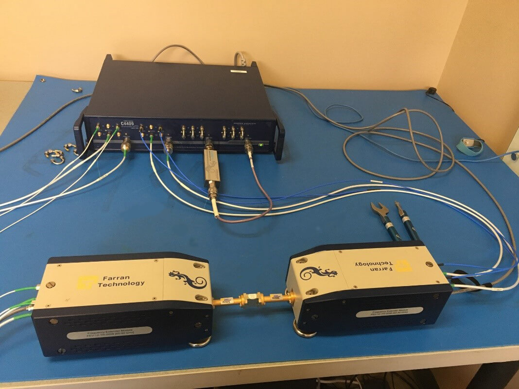
In this example we are using a C4409 VNA to measure a WR12 waveguide bandpass filter with center frequency at 77 GHz and a bandpass filter with center frequency at 500 MHz. We have the CobaltFX FEV-12 extenders connected to port 1 and port 2 of the VNA. These extenders cover the 60 GHz to 90 GHz frequency range.
Figure 1: FEV-12 extenders are shown connected to ports 1 & 2, while ports 3 & 4 are connected to the 500 MHz bandpass filter
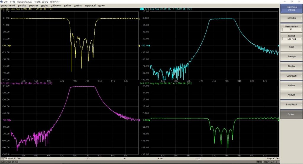
Now we can calibrate and then measure the waveguide filter by reading the port 1 and port 2 measurements.
Figure 2: Measurement of 77 GHz bandpass filter on ports 1 & 2
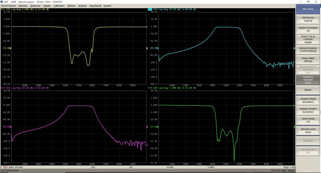
When we want to start measuring the 500 MHz bandpass filter, we simply need to go to Systems>miscellaneous settings> extenders> select “none”. The VNA software at this point will relaunch itself and the frequency range will go back to 100 MHz to 9 GHz. To read the measurements of the 500 MHz filter we need to read measurements on port 3 and port 4.
Figure 3: Measurement of 500 MHz bandpass filter on ports 3 & 4
Conclusion
As you can see this is a fairly simple measurement process, which allows you to quickly make measurements in multiple frequency ranges through the use of a single measurement setup. If you need further clarification on this application note or any assistance with your specific application, please contact: support@18.223.218.127.