
Third Order Intercept
October 30, 2020Introduction
What is IP3?
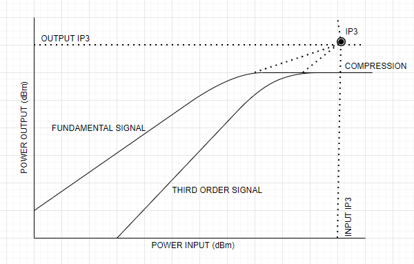
Third order intercept or IP3 is a hypothetical point at which the fundamental signal power and the third order signal power is the same. In practice, we can never reach this point as the amplifier saturates even before this condition occurs. However, IP3 plays an important role in characterizing the device.
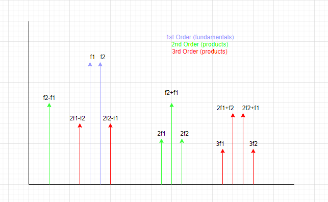
The most troublesome of the intermodulation products are 2f1 ± f2 and 2f2 ± f1 since these frequencies are very close to the fundamental frequency. Those possibly occurring in the amplifier frequency range are 2f1 – f2 and 2f2 – f1. The typical way of dealing with troublesome products is through filtering. But this becomes difficult when the products are very close in frequency to the fundamental signals.
Why do we need to measure IP3?
Calculating the Third Order Intercept is a method of quantifying intermodulation distortion (IMD) and determining the linearity of a device under test. This is important for verifying RF performance.
A high IP3 value specifies that the device has good linearity. But a low IP3 value means the intermodulation products could interfere with the fundamental signal. The IP3 value primarily indicates how large of a signal the amplifier can process before Intermodulation Distortion (IMD) occurs.
If the signals are close together in frequency, some of the sum and difference frequencies (intermodulation products) produced can occur within the bandwidth of the amplifier. These cannot be filtered out, so they will ultimately become interfering signals to the main signals that are to be amplified. That is why every effort must be put into controlling the biasing, signal levels, and other factors to make sure maximum possible linearity is achieved to significantly reduce the intermodulation distortion (IMD) products.
Traditional IMD Measurement using Spectrum Analyzer
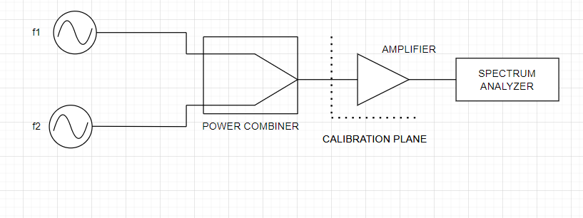
The traditional method of measuring IMD involves the use of two tones. This usually is done at a fixed frequency using signal generators, spectrum analyzer, and a combiner. This is very tedious since measurements must be repeated for various frequencies in the DUT frequency range.
This is where the VNAs come into picture. Automating the IP3 measurement using a Copper Mountain Technologies 4-port VNA simplifies the procedure and allows for quick and accurate results through the entire frequency range, rather than a single point.
The combination of dynamic range and calibration capabilities of a Copper Mountain Technologies 4-port VNA provides exceptional measurement accuracy and speed compared with the traditional spectrum analyzer method.
IP3 Measurement Procedure using Copper Mountain Technologies 4-port VNA
The DUT used for measuring IP3 was Analog Devices Amplifier – H634.
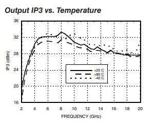
Figure 1: Expected OIP3 Graph for H634
- Adjust the stimulus measurements such as start and stop frequencies, number of points, IF bandwidth, DUT gain etc. in the measurement setup option.
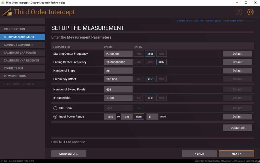
Figure 2: Measurement Setup
- Perform the optional receiver and power calibration.
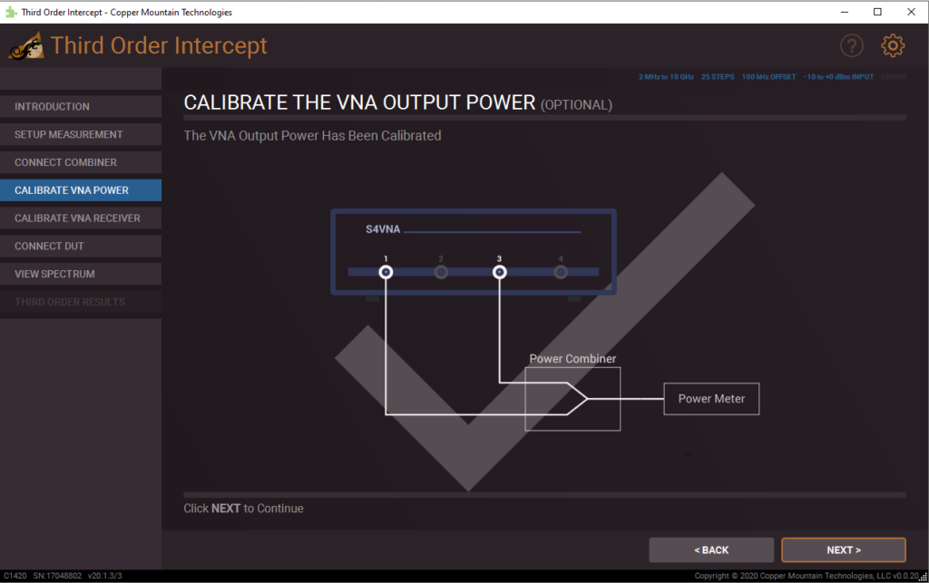
Figure 3: Power Calibration
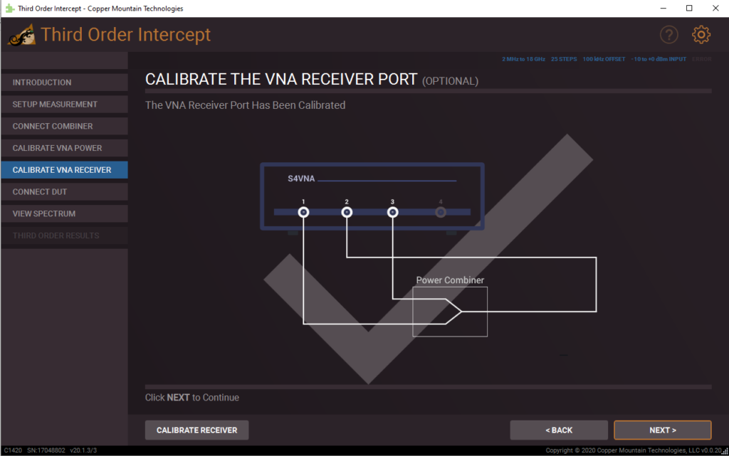
Figure 4: Receiver Calibration
- Once the calibration is performed, go ahead and connect the DUT and measure its spectrum.
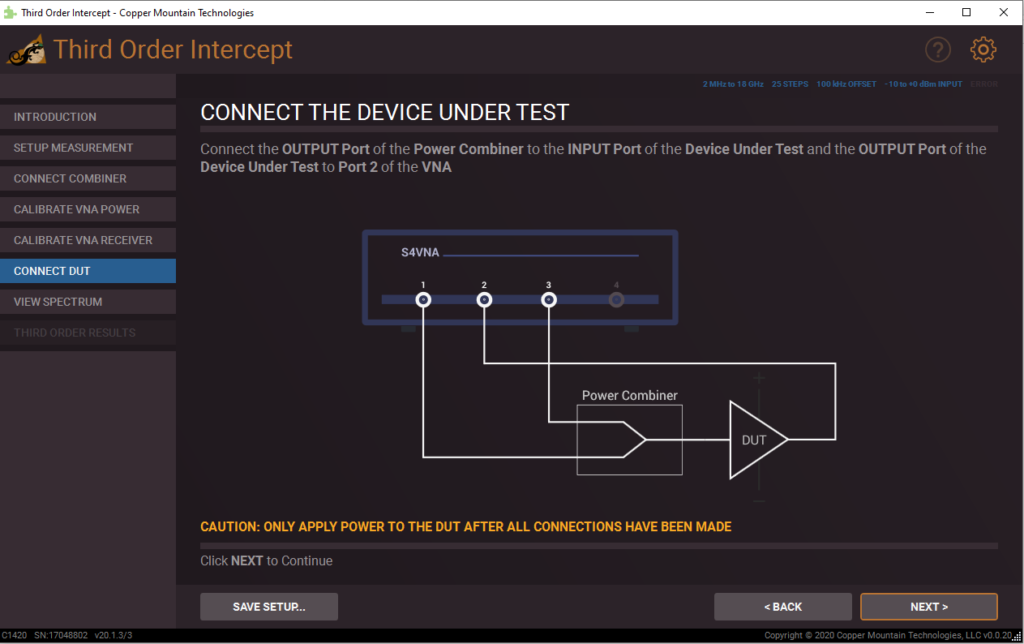
Figure 5: Connecting the DUT
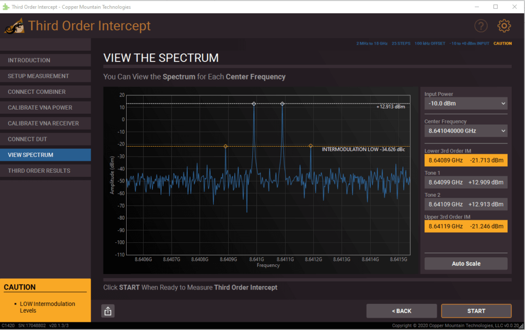
Figure 6: Spectrum Measurement
- The IP3 graph for our measurement is shown below –
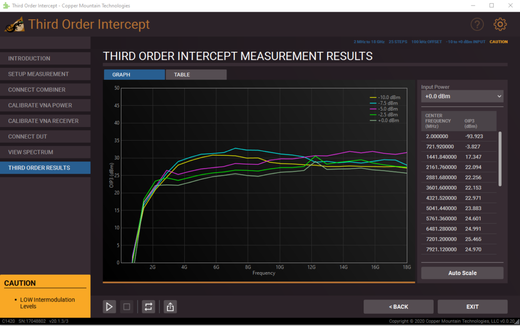
Figure 7: Measured IP3 Graph
X-axis on the graph is frequency and Y-axis is the output IP3. The graph gives information about how the output IP3 changes with various input drives.
Conclusion
With the use of a Copper Mountain Technologies VNA, third order intercept can be easily measured without the hassle of complex setup that features multiple devices. CMT’s Third Order Intercept plug-in provides a simple, straightforward, easy to use, and free application which helps engineers with the design, development, and qualification tasks. This free plug-in is available for download from Copper Mountain Technologies website. For further inquiries about this plug-in, please email us at support@18.223.218.127.
